
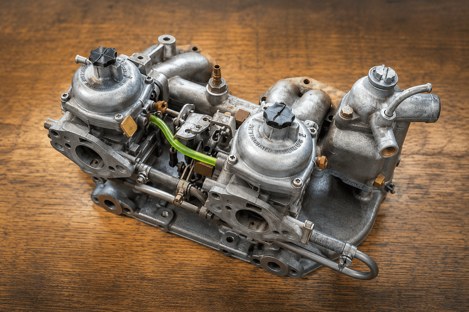
If the SU carburettor is the British classic car world’s most celebrated variable-choke unit, the Zenith-Stromberg is its slightly less glamorous sibling: broadly similar in operating principle, different in construction, and fitted to a significant proportion of the cars that crossed the Atlantic from the late 1960s onward. The Stromberg arrived because American emissions regulations were becoming increasingly hostile to the SU, and Zenith’s engineers produced a solution that met the requirements while retaining the constant depression principle that made variable-choke carburettors so effective. The result is a carburettor that works beautifully when properly maintained and drives its owners to distraction when it is not. This guide will put you firmly in the first category. Our SU carburettor guide covers the HS and HIF units; this one is for the Stromberg and the owners who have one, whether by choice or by the accident of having bought a US-specification TR6 and discovered the fact only after the paperwork was signed.
One point before anything else, because it governs everything that follows. The Stromberg is not one carburettor. It is a family of them, and the family divides into two camps that are tuned by opposite methods. Work out which camp yours belongs to before you pick up a tool. There is a section below devoted to exactly that, and skipping it is the single most reliable way to waste an afternoon.
Which cars have Strombergs
The Zenith-Stromberg CD series was fitted to a range of British classics, predominantly in US-market specification but not exclusively. Common configurations include:
- Triumph TR6 (US specification): twin 175 CD carburettors in place of the Lucas mechanical fuel injection of the home-market car. The headline figures are 150bhp for the injected car and 104bhp for the carburettor version, though the two are not measured the same way: the 150 is a gross figure and the 104 a net one, so the real-world gap is smaller than the arithmetic suggests. It is still a gap, and American TR6 owners have had four decades to come to terms with it. Our TR6 specs and values guide covers the specification differences in full.
- Triumph GT6: twin 150 CD units, on all GT6s regardless of market. The Vitesse used 150 units too
- Triumph Spitfire: single 150 CD on US-market cars, moving to emission-controlled variants later. Home-market Spitfires ran twin SUs, so a single Stromberg on a Spitfire is a strong hint that you are looking at an American car
- Triumph Stag: twin 175 units, appearing as CD2S, CDSEV and CD2SEV across the production run
- Triumph 2000 and 2500 saloons: 175 CD2 units on carburettor-equipped versions
- Triumph TR7 and TR8: twin 175 units on the relevant market specifications
- MGB (North American market, 1975 to 1980): single 175 CD5T with automatic choke, replacing the earlier twin SU arrangement that the Americans were not allowed to have any more
- MG Midget 1500 (North American market): single 150 CD4 or CD4T. Note that this is a 150 and not a 175, despite the Midget and MGB being routinely lumped together in parts listings
- Jaguar E-Type Series 2 and Series 3, and various XJ models: 175 CD2 and CD2SE units
- Rover V8 applications including the Range Rover: 175 CD2S and related units
- Federal-specification Lotus models: CD and CD2SE units
The family reaches well beyond British cars, incidentally. Volvo and Saab both used 175 units into the 1980s, which is why Stromberg parts turn up in Scandinavian catalogues and why some components are easier to source than the model-specific listings suggest.
Strombergs are identified by a number and letter code. The number (125, 150, 175) indicates the choke diameter in fractions of an inch: 1¼, 1½ and 1¾ respectively. The size makes no difference whatever to the tuning method. The letters are what matter.
CD, CDS and CD2S are the pre-emission versions found on most classic British cars. The suffix E, as in CDSE and CD2SE, denotes an emission-controlled version. The CDSE series introduced biased spring-loaded metering needles, cable-operated starter boxes, temperature compensators and bypass valves. The CDSEV added a float chamber vent valve. The CDST, CD4T and CD5T families use a thermostatically operated water choke, which is why an MGB of the late 1970s has a carburettor plumbed into the cooling system and a Spitfire of a decade earlier does not.
A word of warning that will save you some frustration: Strombergs are not reliably stamped with their type mark. A number stamped or tagged on the body is usually a part number rather than a type designation. The handbook or workshop manual for your specific car will normally tell you, but the physical check in the next section is faster and more certain.
Identifying which type you have
Everything about the mixture adjustment depends on this, so do it first. The two camps are the adjustable-jet types and the fixed-jet types, and no standard Stromberg is both.
Look underneath the carburettor body. A screw or hexagon set centrally in the base, surrounding the jet, means an adjustable jet. This is a CD, CDS or CD2S. The jet moves up and down against a needle that is clamped in the air valve and does not move.
Look down the damper tube. Remove the damper rod and look into the hollow tube. An adjuster socket at the bottom means an adjustable needle. Combined with a plain body carrying no adjuster underneath, this is a CDSE or one of its relatives. The jet is pressed into the body, set at the factory and not adjustable in standard form. The needle moves instead.
Look closely at that socket before ordering a tool, because there are two patterns and they are not interchangeable. Some units take a hexagonal key (the tool is Zenith part B20379, usually described as the Allen key type) and others take a raised blade (part B25860, the slotted type). Buying the wrong one is a common and avoidable annoyance.
As a rough dating guide, the fixed-jet arrangement came in around 1971 and ran to the end of production, so a carburettor from the 1960s is very likely to be an adjustable-jet type and one from the late 1970s very likely not. Treat that as a prompt to check rather than as a substitute for checking, since carburettors get swapped between cars far more often than the original build records suggest.
If you find an adjuster in both places, you are looking at a fixed-jet carburettor that somebody has converted with an aftermarket adjustable jet. These conversions are sold by several specialists and are a perfectly sensible modification, particularly on a worn engine, but they mean the standard procedures no longer apply cleanly and you should follow the conversion supplier’s instructions for the jet while using the needle procedure below for the needle.
Two consequences follow from this identification, and they matter more than anything else in this guide:
- Jet centralisation applies only to the adjustable-jet types. On a CDSE the needle is deliberately spring-biased so that it rides against one wall of the jet orifice. This is by design. Such a carburettor will never produce the sharp click that indicates a centred jet on a CD, and attempting to chase that click will consume an evening and achieve nothing.
- The mixture is set in completely different places. Jet screw underneath on one, needle adjuster down the damper tube on the other. Instructions for one type applied to the other will not work, and a good deal of the confusion surrounding these carburettors comes from workshop advice that fails to say which type it is describing.
How the Stromberg works: the important differences from the SU
Like the SU, the Stromberg is a constant depression carburettor. A variable-choke venturi, an air valve (the Stromberg’s name for its piston) that rises and falls to maintain constant pressure across the jet, and a tapered metering needle controlling fuel delivery across the throttle range. The operating elegance is identical to the SU and stems from the same insight: that a self-regulating system produces better results across a wider range of conditions than a fixed-choke carburettor trying to cover different operating conditions with multiple fixed jets.
The critical constructional difference is the diaphragm. Where the SU uses a solid piston sliding in a machined bore, the Stromberg air valve is surrounded by a thin rubber diaphragm that seals the suction chamber from the atmosphere. This is the component that defines Stromberg ownership. The diaphragm must flex freely and seal perfectly at all times. A pinhole, a tear, or a diaphragm that has hardened with age will produce symptoms ranging from mild rough running to fuel spitting from the vent pipe and a complete inability to idle. Every Stromberg diagnosis starts with the diaphragm. Every single one. Not the needle. Not the jet. The diaphragm. Write it on your hand if that helps.
The second important difference is the mixture adjustment, which as established above depends on which type you have. On an SU, mixture is always adjusted by moving the jet relative to the needle. On a Stromberg it may be either: the adjustable-jet types work much as an SU does, while the fixed-jet emission types invert the arrangement and move the needle instead. Anyone approaching their first Stromberg with confident SU habits will find one type broadly familiar and the other completely foreign.
The one tool you actually need
If you have a fixed-jet type, adjusting the needle means reaching an adjuster at the bottom of the damper tube with a long key. The problem is that turning that key without restraining the air valve imparts a twisting force on the diaphragm that can tear it. This is not a remote theoretical possibility. It happens with sufficient regularity that Zenith designed a specific adjustment tool to prevent it: a thick-walled outer tube with a pin on its side that drops into a slot in the air valve shaft, holding the valve stationary while the inner key turns the needle adjuster.
Buy the pattern that matches your carburettor, hexagonal or slotted, as described in the identification section above. In use, seat the outer tube first and confirm the pin has engaged the slot, then hold the outer tube firmly with one hand throughout while turning the inner key with the other. Holding the tube is not a refinement. It is the entire point of the tool.
The tool is inexpensive and available from Moss Europe, Rimmer Bros, SC Parts and Burlen Fuel Systems, who supply Zenith and SU components. It pays for itself immediately by not costing you a new diaphragm and three hours of unexplained frustration. Buy it before you need it. The alternative, if the tool is genuinely not to hand, is to remove the dashpot cover completely, lift the air valve out, make the needle adjustment while holding the assembly safely in your hand, and reassemble. Slower, more steps, perfectly legitimate, zero diaphragm risk. What is not legitimate is inserting a bare key without the tool and hoping that this time it will be fine. It will not be fine. The diaphragm will demonstrate this at a time and location of its own choosing.
You will also need: a small coin or wide flat screwdriver for the jet adjusting screw if you have an adjustable-jet type, a tachometer for idle speed, SAE 20 or engine oil for the dashpot damper, a timing light, and a set of Pozidriv bits. That last item is not a pedantic distinction. The screws on these carburettors are Pozidriv rather than Phillips, a Phillips driver does not seat properly in them, and using one is how the dashpot cover screws come to be rounded off on so many otherwise well-kept cars.
Finally, genuine patience about warming the engine fully before touching anything. All carburettor adjustments on a Stromberg are made at full operating temperature. Adjustments made on a cold engine are accurate for a cold engine and meaningless for a warm one, which is the only condition the car actually spends most of its time in.
Step one: inspect the diaphragm
Remove the air cleaner. Undo the dashpot cover screws: typically four or six small screws set in aluminium, which means they are the kind of screws that strip if approached with anything more forceful than polite intent. Use a correctly fitting Pozidriv driver and apply firmness rather than enthusiasm. Lift the cover carefully and inspect the diaphragm under a bright light, holding it up to check for pinholes as well as visible tears. Check the edges where the diaphragm seats in its groove, the area around the two moulded tabs, and the centre where the air valve rod passes through. Any damage at all means replacement before proceeding.
A lesser-known issue worth knowing: if the diaphragm has been in contact with moisture or cleaned with anything damp, it may have swelled slightly and will not seat correctly in its groove until it has dried at room temperature. A diaphragm that looks intact but fits loosely or will not settle in its recess needs an hour to dry, not more persuasion. And never use solvent-based cleaners, strong carburettor cleaner, or trichloroethylene anywhere near a Stromberg diaphragm. Paraffin on a clean cotton rag is the approved method, applied gently. The diaphragm was not designed to resist aggressive chemistry and will make this clear if you test the theory.
Replacement diaphragms are not expensive and are available from all the major British car parts suppliers. Fitting a new one takes ten minutes and transforms the tuning process from an exercise in mounting frustration into a procedure that actually produces consistent results. Keep a spare in the glovebox if you use the car regularly. A diaphragm that fails forty miles from home on a Saturday afternoon produces a very specific and entirely preventable kind of afternoon.
Fitting a replacement diaphragm: the details that matter
The diaphragm has two moulded tabs, one on the inner diameter and one on the outer. The inner tab engages with a slot in the air valve. The outer tab engages with a slot in the carburettor body. Both tabs must be correctly located before the cover goes back. An incorrectly oriented diaphragm will either prevent the air valve from moving freely or will tear within minutes of the first engine start. Take the time to confirm both tabs are properly seated before tightening a single screw.
Those tabs are doing more work than they appear to. There are two small holes in the bottom rim of the air valve, and their job is to transfer manifold vacuum up into the chamber sealed by the diaphragm, which is what lifts the air valve in the first place. They must sit on the engine side of the jet, between the jet and the throttle plate. Fit the air valve the other way round, with the holes facing the intake, and the vacuum signal never reaches the chamber and the air valve simply does not rise. The carburettor then behaves in a way that is genuinely difficult to diagnose unless you know this specific detail exists. The useful part is that locating the diaphragm tabs correctly puts the holes on the correct side automatically, so getting the tabs right solves both problems at once.
When refitting the dashpot cover, tighten the screws in a cross pattern to ensure even seating of the diaphragm bead all the way around. Overtightening strips the threads in aluminium. Undertightening leaves an air leak at the cover joint that produces lean running identical in symptoms to several other causes. Snug and even is the target.
Step two: check the dashpot damper
The dashpot damper slows the rise of the air valve under sudden throttle opening, providing a momentary enrichment that prevents the flat spot otherwise caused by the needle lifting too quickly out of the jet. Without a working damper the engine hesitates on acceleration in a way that no mixture adjustment will cure, because the problem is the rate of valve travel rather than the mixture setting itself. Many a carburettor has been unnecessarily rebuilt because the damper was empty and nobody checked it first.
Remove the damper rod from the top of the dashpot and check the oil level in the hollow tube. It should be within about 6mm of the top. Top up with SAE 20 or engine oil. Zenith specified their own product but any clean engine oil of similar weight works perfectly well.
A lesser-known refinement: the viscosity of the damper oil affects throttle response character. Heavier oil produces more pronounced damping and a slightly fuller response at the bottom of the throttle range. Lighter oil gives a quicker, crisper response. Most owners use straight engine oil and are perfectly satisfied. If the car hesitates on very rapid throttle blips despite correct mixture and a full damper, experimenting with a slightly heavier oil is worth trying before suspecting anything more fundamental.
Step three: check the float chamber and fuel level
This step is skipped by almost everyone and causes problems for a disproportionate number of people. The float chamber maintains a constant fuel level that underpins correct mixture delivery across the entire operating range. Too high and the carburettor runs rich regardless of needle position. Too low and it runs lean under load regardless of how carefully everything else has been set. Both conditions can be tuned around to a degree at idle, but the mixture will be wrong across the rest of the throttle range and no amount of adjustment elsewhere will compensate for an incorrectly set float level.
To check: remove the float chamber from the base of the carburettor, invert it, and check the position of the floats relative to the chamber face. The correct dimension varies by model and by application, and this is one figure that genuinely must come from the workshop manual for your specific car rather than from a general guide. Adjust by carefully bending the tang on the float arm that contacts the needle valve, working in very small increments and rechecking after each adjustment.
While the float chamber is removed, inspect the float needle valve. This small spring-loaded valve controls fuel entry to the chamber and is a known weak point on all Strombergs. A valve that sticks open allows the chamber to overfill and produces rich running that no mixture adjustment can correct. A valve that sticks closed starves the engine under load. Cars that stand for months at a time on ethanol-blended fuel suffer this most, which is a clue as to the underlying cause.
Two replacement options exist and the choice between them is genuinely contested, so it is worth setting out honestly rather than picking a side. The Viton-tipped needle valve is the conventional replacement and is what most rebuild kits contain. The Grose jet substitutes a ball valve for the needle and seat, passes more fuel, and is favoured by owners who have had repeated trouble with sticking needle valves. Against that, a number of experienced hands report that Grose jets stick at least as often as Viton items, that recent production is less consistent than the originals, and that a ball seating slightly off-centre will leak reliably. At least one Stromberg specialist removes them on sight.
The sensible reading is that neither is a cure for a carburettor that stands full of ethanol-blended fuel for six months, that either works well when clean and correctly seated, and that if the one you have is giving trouble the other is worth trying. What matters far more than the choice is that the float arm pushes squarely on the valve, because a valve loaded off to one side will leak whichever type it is.
This is also the moment to consider fuel compatibility. Ethanol attacks period rubber and can dissolve the solder in an original float. Our fuel system guide covers E10 and the ethanol-resistant components now available for these carburettors.
Step four: check jet centralisation (adjustable-jet types only)
This step applies to CD, CDS and CD2S carburettors. Skip it entirely if you have a CDSE or another fixed-jet emission type, for the reasons given earlier: the biased needle on those units is meant to touch the jet wall and will never give a clean click.
On an adjustable-jet carburettor, confirm that the jet orifice is correctly centred beneath the needle before adjusting mixture. With the air cleaner removed, lift the air valve by hand and allow it to fall. If the jet is correctly centred the valve falls with a sharp, decisive click as the needle enters the orifice cleanly. A soft thud, a muffled drop, or an absent click indicates the needle is fouling the jet walls. No mixture adjustment will produce correct results until this is resolved. Attempting to tune such a carburettor with an off-centre jet is like trying to tune a piano with a hammer: the motions are broadly correct but the outcome is not what anyone wanted.
To re-centre: with the dashpot cover screws tight so the air valve is correctly located, remove the damper rod and insert a pencil firmly down the hollow tube to hold the air valve down, so that the needle sits in the jet and defines the correct position. Slacken the jet assembly half a turn to free the orifice bush, allow it to settle around the needle, then retighten. Recheck by lifting and dropping the air valve. Repeat until the click is sharp and consistent.
Step four for fixed-jet types: check the jet height after a rebuild
Fixed-jet types have no centralisation procedure, but they do have an equivalent trap, and it catches people specifically during a rebuild rather than during routine tuning.
The pressed-in jet on these carburettors sits at a specified depth below the bridge of the throttle bore. That depth is a real dimension, set at manufacture, and it can be disturbed if the jet has been pressed out and back in during an overhaul, or if a previous owner has been experimenting. Get it wrong and the carburettor may still run, but the needle adjustment will be working from the wrong starting point. The characteristic symptom is running out of adjustment: you reach the rich stop or drop the needle out at the lean end without ever finding a setting that gives a correct lifting pin response.
If you have rebuilt the carburettor, or inherited one that somebody else rebuilt, and the needle adjustment will not reach a sensible mixture anywhere in its travel, suspect the jet height before suspecting the needle. Jet setting tools for the fixed-jet carburettors are available from Stromberg specialists, and the correct depth for your application comes from the workshop manual. This is not a routine service item and most owners will never need to touch it, but it is the answer to a problem that otherwise looks insoluble.
Step five: confirm ignition timing before touching the carburettors
Check the ignition timing before adjusting the carburettor. A correctly set carburettor on incorrectly timed ignition will need re-setting when the timing is eventually corrected. Establishing the correct timing first means the carburettor setup is done once rather than twice. Our ignition timing guide covers the full procedure.
With timing confirmed, warm the engine to full operating temperature. Leave the air cleaner fitted throughout the tuning process wherever the design allows. The Stromberg was calibrated to work with its original air cleaner in place, and an aftermarket filter of different dimensions alters the airflow characteristics and produces a carburettor that is correctly set for the filterless condition and wrong for the normal running condition. Fit the original or a correctly specified replacement, and leave it in place while you work.
Step six: set the idle speed, then the mixture
With the engine at operating temperature, set the idle speed using the throttle stop screw before adjusting mixture. For most applications 850 to 950rpm is the target, but check your handbook, as some cars specify considerably lower. On twin carburettor installations, adjust only the primary carburettor’s throttle stop screw at this stage.
Now go to whichever of the following two sections matches your carburettor.
Adjustable-jet types: the jet adjusting screw
The jet adjusting screw is set centrally in the base of the carburettor body. A small coin gives better feel than a screwdriver and reduces the chance of the tool slipping. The principle is simple and worth holding onto in preference to memorising a direction: raising the jet weakens the mixture, lowering it richens the mixture. On most units this means clockwise as viewed from beneath weakens and anti-clockwise richens, but carburettor variants differ, so confirm which way yours behaves by its effect on the engine rather than trusting the direction alone.
Make adjustments of one eighth of a turn at a time, wait for the engine speed to stabilise, and assess before making the next change. Patience here produces accurate results. Haste produces a carburettor that has been adjusted several times in quick succession and is now in an unknown state relative to where it started, which is its own special kind of problem.
Fixed-jet types: the needle adjuster
With the proper Stromberg tool engaged so that the air valve cannot rotate, turn the key clockwise to raise the needle and richen the mixture, anti-clockwise to lower it and weaken the mixture. The available range is commonly around three turns, though it varies by unit and some carburettors give appreciably more, so treat three as an expectation rather than a specification.
There is a hard stop at the full rich end and no stop at the lean end, which means turning too far anti-clockwise disengages the needle from the adjuster and drops it into the jet. The engine will then run as though several important decisions were made without adequate consultation. The cure is removing the dashpot cover, recovering the needle, and resetting from the rich stop.
The baseline setting for a standard engine in good condition is to turn fully clockwise to the rich stop and then back off approximately one and a half turns, though you should confirm the figure against your workshop manual as applications vary.
A word on the “flush” reference that circulates widely and is easy to misapply. The factory procedure uses it for installing a needle: with the air valve out, the needle is wound in with the tool until its shoulder is flush with the base of the air valve, and the lock screw is then tightened. That is the fitting datum, and it is where you start from after replacing a needle. It is not a statement that a correctly tuned carburettor sits flush, and treating it as a tuning target rather than an assembly reference will send you looking for a setting that does not exist.
A third adjuster: the fine mixture trim screw
Some emission-specification carburettors carry a fine mixture trim screw in addition to the needle adjuster, and the factory tuning sequence uses it before touching the needle at all. The order is: set idle speed and equalise airflow, then bring the mixture into specification on the trim screw, and only if that fails to get there, move the needle. Clockwise on the trim screw richens.
If your carburettor has one, use it. Reaching straight for the needle when a trim screw is fitted means making a coarse adjustment where a fine one was intended, and on twin installations the factory is explicit that the needles must be turned by equal amounts on both carburettors if you do move them.
The lifting pin test
The lifting pin test assesses mixture strength at idle and applies to both types. With the engine at operating temperature, locate the lifting pin beneath the edge of the dashpot. Not all Strombergs have one; if absent, use a long slender screwdriver or stiff wire to lift the air valve approximately 1mm, no more. Then observe the engine speed:
- Speed rises and stays up while the valve is held: mixture is too rich. Weaken it and retest.
- Speed drops immediately, or the engine threatens to die: mixture is too weak. Richen it and retest.
- Speed rises very slightly for a moment then settles back to normal: mixture is correct.
The logic is worth understanding rather than memorising, because it is easy to invert. Lifting the air valve admits a rush of extra air. If the engine was already running rich, that extra air is exactly what it was short of, so it speeds up and stays fast. If the engine was already lean, more air is the last thing it needs and it falters. A correct mixture gives the brief lift and immediate recovery.
The correct response is genuinely brief, often less than a second, and detecting it takes practice. If you cannot read it reliably, an alternative that many experienced hands prefer is to richen until the idle speed begins to fall, note the position, weaken until it begins to fall again, and set the mixture midway between the two. Work toward the result in small increments either way.
Where the two adjustments interact, recheck. On an adjustable-jet carburettor the mixture and idle speed affect one another, and on a fixed-jet carburettor a significant needle change will alter the idle enough to require a compensating tweak to the throttle stop.
Balancing twin carburettors
Twin Stromberg installations on the TR6, Stag and others require balancing as well as individual mixture tuning. Both carburettors feed different cylinders, and if they are not flowing equal volumes of air the engine will idle unevenly and perform inconsistently regardless of how carefully each unit was set up on its own. Balancing cannot be substituted with a better mixture setting. It is a separate step requiring a specific tool, and skipping it on a twin carburettor car is the equivalent of tuning two instruments separately and wondering why the duet sounds peculiar.
The tool needed is a carburettor airflow meter. The Gunson Carbalancer is the traditional choice: a device held against each carburettor air intake in turn that displays airflow on a dial. The Uni-Syn is a popular American alternative, widely used by TR6 owners. The Morgan Carbtune is the more refined option for the owner who takes these things seriously, using manometers rather than a mechanical gauge for greater precision. All work on the same principle of measuring and comparing the airflow through each carburettor.
A ColourTune spark plug is a useful separate tool for confirming mixture quality on each cylinder by observing combustion colour through a transparent plug body. Blue indicates correct mixture, yellow indicates rich, and white flashes indicate lean. It is not an airflow meter and cannot be used to balance carburettors against each other. The distinction matters because the two tools are occasionally confused, and using a ColourTune where a flow meter is needed produces no useful balancing information and the mild bewilderment of having done something technically correct for the wrong purpose.
Balancing procedure: with both carburettors individually tuned and the engine at operating temperature, hold the flow meter against each carburettor air intake and compare readings. They should be equal. If they are not, adjust the throttle stop screw on the secondary carburettor until its airflow matches the primary. Recheck overall idle speed and adjust the primary throttle stop screw if necessary to restore the correct rpm. Then recheck balance. The two affect each other slightly and may need one iteration to settle.
Once balanced at idle, blip the throttle and allow the engine to return to idle. It should settle quickly and evenly. A car that idles smoothly but stumbles on the return from a blip often has carburettors that are balanced at idle but diverging on the overrun, which points to unequal damper oil levels or differing mixture settings between the two units. Check the damper oil is at the same level in both before pursuing anything more complicated.
After balancing, repeat the lifting pin test on each carburettor individually. Throttle adjustments made during balancing can alter idle mixture slightly, and confirming both units are still correctly set after the balancing process ensures the whole setup is consistent rather than correct in isolation.
The fast idle, choke, and seasonal adjustment
The fast idle stop screw provides increased idle speed when the choke is engaged. With the choke fully pushed home, in the normal warm running position, there should be a gap of approximately 1mm between the fast idle screw head and the choke cam, though you should set the figure your car’s manual specifies. If this gap is absent, the fast idle screw is holding the throttle slightly open at all times, producing a persistently elevated idle speed that no amount of throttle stop screw adjustment will fully cure. This is worth checking on any car where the idle speed seems reluctant to come down to the correct figure despite apparently correct throttle stop setting.
Cold start arrangements differ across the family. The earliest CD units used a starter bar acting as a true choke. Later units use a rotating disc starter device, and the CDSE series uses a cable-operated starter box. The adjustment principle is the same in each case even though the mechanism is not.
Some Strombergs have a two-position fast idle screw with a spring under its head. This is a seasonal adjustment provided by Zenith: with the spring compressed the fast idle is reduced for summer use; with the spring released the full fast idle is available for cold winter starting. This feature is rarely discussed in mainstream workshop guides and can cause puzzling cold-start behaviour on a car that has been correctly set up for summer and then asked to start on a cold January morning with the spring in the wrong position. If cold starting is inconsistently poor despite everything else being correct, check whether this adjustment exists on your carburettor and what position it is in.
The CDST, CD4T and CD5T families use a water-heated automatic choke that opens as coolant temperature rises. Two designs exist. The bimetal spring type uses a temperature-sensitive coil in a water-jacketed heat mass, with a datum mark on the heat mass that must align with the mark on the choke body; if those marks are out of alignment the choke will never behave correctly no matter what else is adjusted. The later wax capsule type works instead as a miniature constant depression carburettor in its own right, with a wax element moving a throttle valve and metering needle together.
Either design is a sensible piece of engineering or a source of ongoing entertainment depending on the condition of the water connections and the temperature-sensitive element. A stuck automatic choke produces rich running that gradually improves as the engine warms, which is the reverse of most other richness symptoms and catches people out regularly. If the car runs poorly rich when cold and increasingly better as it warms, the automatic choke is the first suspect, not the carburettor itself. Manual choke conversions are available for these units and are a popular modification among owners who have wearied of the original.
What the factory said not to touch
Worth knowing before an overhaul: the manufacturer listed four items as not to be changed in service, on the basis that they are matched to the carburettor and cannot be substituted individually. Those are the jet assembly, the air valve, the depression chamber cover, and the type of metering needle. Where one of these is genuinely at fault, the correct remedy is a sub-assembly or a complete carburettor rather than a part swap.
The metering needle is the partial exception. Replacing a needle of the same type is permitted provided the installation procedure is followed properly, which means winding it in until the shoulder sits flush with the base of the air valve and then tightening the lock screw. Fitting a different needle type is a different matter and was reserved for specified circumstances such as high altitude operation.
The temperature compensator
Emission-controlled Strombergs are commonly fitted with a temperature compensator: a tapered valve controlled by a bimetal strip that opens as engine bay temperature rises, admitting air that bypasses the bridge. The mechanism is worth understanding because it does not simply dilute the mixture. The bypassed air weakens the depression over the jet, which lets the air valve fall slightly, which cuts the fuel drawn. The leaning is achieved through the air valve rather than around it. On some applications the compensator is replaced instead by a separate downstream idle circuit or an emulsion circuit serving both idle and main feeds, achieving similar temperature insensitivity by other means, so a carburettor with no compensator is not necessarily missing one. In practice a compensator that has aged, stuck, or been incorrectly adjusted introduces a lean condition at high operating temperatures that is indistinguishable in symptoms from several other faults.
If the car runs correctly when cold but leans off and runs roughly after extended running or in warm weather, and the diaphragm is sound, cooling system functioning, and ignition timing confirmed, check whether a temperature compensator is fitted and whether it is operating correctly. A compensator stuck open bleeds air continuously and causes persistent lean running. One stuck closed provides no temperature compensation and causes over-richness in hot conditions. Many owners of compensator-equipped cars ultimately disable or remove them, accepting the minor mixture variation that results, on the basis that a known fixed quantity is less troublesome than an unknown variable one.
The bypass valve
Emission-equipped Strombergs frequently include a throttle bypass valve, sometimes called an overrun valve. Its purpose is regularly misunderstood, including in places where it ought not to be, so it is worth stating plainly.
The bypass valve is not an anti-run-on device. It exists to deal with what happens on the overrun: when the throttle is snapped shut at speed, manifold depression becomes extremely high and the mixture in the manifold becomes too rich to burn properly. The valve opens under that high depression and allows mixture to bypass the closed throttle plate, so that the charge burns in the cylinder rather than passing through the engine raw and igniting somewhere less convenient. It is an emissions device, and a secondary effect is that it limits the peak depression the engine sees on the overrun.
The symptoms of failure follow from that function and are not the ones you might expect. A valve that fails to open produces popping and banging in the exhaust on sudden deceleration or on downshifts. A valve that sticks open, or a leaking bypass valve gasket, admits air continuously and produces an idle that hangs several hundred rpm above where it should be and cannot be brought down with the throttle stop screw. That hanging idle is the classic sign, and it is worth checking before pursuing more exotic explanations for an idle that will not settle.
The valve is adjustable, and the factory procedure gives figures worth knowing even if you never touch the screw. With the engine warm and the distributor vacuum pipe disconnected and plugged, a correctly operating valve lets the engine speed rise to around 1300rpm. A valve that is floating sends it abruptly to 2000rpm or beyond. On twin installations one valve must be shut off completely before the other can be set. If yours is producing a hanging idle, that test tells you which valve is at fault before anything comes apart.
Blanking the valve off with a solid gasket is a common modification and will require the idle to be reset afterwards.
Worn needles and jets: when adjustment is not enough
If the lifting pin test shows correct mixture at idle but the car runs rich on acceleration and lean at light throttle, or the mixture seems broadly correct but varies unexpectedly with throttle position, the needle and jet may be worn beyond the point where adjustment can compensate. The needle wears at its mid-section where it spends the most time in the jet orifice, and the jet wears from round toward oval as the needle vibrates against its walls over many thousands of miles. A worn jet cannot be adjusted into correct behaviour because the clearance between needle and orifice varies depending on the needle’s vertical position, making the mixture different at different throttle openings regardless of the adjustment setting.
Check the needle by rolling it on a flat glass surface: a bent needle will rock rather than roll true. Inspect the mid-section for wear steps or a polished worn area. A bent or worn needle should be replaced and is specified by a code marked on the needle itself. Note that the biased needles used in CDSE units are a distinct family and are not interchangeable with the plain needles of the earlier carburettors, so quote the code rather than the carburettor size when ordering.
Replace the jet at the same time where the design permits: fitting a new needle in a worn jet improves matters but does not resolve the fundamental issue, and the next time the carburettor comes apart you will be doing this job again.
Confirm with a plug reading
After completing the full tuning sequence, read the spark plugs after a run that includes some load and varied throttle. A correctly tuned Stromberg should produce plugs with a light tan to grey-brown colour on the insulator nose. Black sooty deposits indicate persistent over-richness. White or very pale grey indicates sustained leanness. The plugs tell you what the mixture has actually been doing across the full operating range in real conditions, not just at the idle point where the lifting pin test was made. Our spark plug diagnosis guide covers the full range of conditions and what each indicates.
Common faults and what they actually mean
- Fuel spitting from the vent pipe or air intake: almost certainly a torn diaphragm. Start here before investigating anything else, without exception.
- Air valve does not rise at all: air valve fitted the wrong way round, with the two vacuum holes facing away from the engine. Check the diaphragm tab alignment.
- Rich running that does not respond to adjustment: torn diaphragm, float needle valve stuck open, float level set too high, or automatic choke stuck. Check in that order.
- Lean running that does not respond to adjustment: air leak at the base gasket, inlet manifold gasket, dashpot cover, temperature compensator, or bypass valve gasket. The adjusters cannot compensate for an air leak. Find the leak and fix it first.
- Idle hangs several hundred rpm high and will not come down: bypass valve stuck open or its gasket leaking, or fast idle screw holding the throttle open. Not a mixture problem.
- Popping in the exhaust on deceleration or downshifts: bypass valve failing to open.
- Sticking air valve: carbon or dirt on the air valve outer diameter or in its bore. Clean with paraffin on a clean rag only. Check the needle is straight by rolling it on a flat surface. Confirm diaphragm tabs are correctly aligned and not obstructing movement.
- Idle that will not settle despite apparently correct mixture: incorrectly aligned diaphragm tabs, needle dropped from the adjuster, dashpot cover not seating evenly, or a stripped cover screw allowing an air leak.
- Hesitation on acceleration despite correct idle mixture: empty or low dashpot damper. Check this before anything else. An empty damper is responsible for more unnecessary carburettor rebuilds than any other single fault.
- No sharp click when the air valve is dropped: on an adjustable-jet type, the jet needs centralising. On a fixed-jet emission type, this is normal and expected. Establish which you have before chasing it.
- Needle adjustment runs out of range without ever finding a correct mixture: on a rebuilt fixed-jet carburettor, suspect the jet height rather than the needle.
- Needle dropped from adjuster: turned too far anti-clockwise toward lean. Remove the dashpot cover, retrieve the needle, reset from the full rich stop, and approach the lean direction more cautiously this time.
- Runs rich when cold, improves as engine warms: automatic choke stuck or slow to open. Not a mixture adjustment problem.
- Runs correctly cold, leans off when hot: temperature compensator stuck open, or cooling system not maintaining correct temperature. Confirm thermostat function before blaming the compensator.
The Stromberg in honest perspective
The Zenith-Stromberg’s reputation for difficulty is largely inherited from three things: decades of neglected diaphragms, adjustments attempted without the correct tool, and guidance that fails to distinguish between the adjustable-jet and fixed-jet types and so sends owners looking for adjusters their carburettor does not possess. None of those is a fault of the carburettor.
A Stromberg with a sound diaphragm, correct float level, full damper, correctly oriented air valve and properly set mixture is a composed and effective carburettor that provides smooth, progressive fuel delivery and an idle that settles consistently. The operating principle is elegant and the construction is robust.
The practical maintenance difference from the SU is simply that the diaphragm is a service item requiring periodic inspection and occasional replacement, where the SU’s solid piston just needs keeping clean. Identify your type before you start, build diaphragm inspection into your annual service, keep a spare for long runs, do not attempt needle adjustment without the tool, and check the damper before suspecting anything complicated. Do these five things and the Stromberg will reward you with years of reliable service. Ignore any of them and it will demonstrate, with unhurried patience, exactly why each one was on the list.
Going to the source
Much of what circulates about these carburettors is second-hand, and some of it is second-hand from something that was wrong to begin with. If you want to check anything in this guide, or settle an argument about your own car, the British Leyland training aid Zenith-Stromberg factory tuning manual is available as a free PDF through the Triumph Wedge Owners Association. It covers the emission-specification carburettors in detail, with exploded diagrams, the adjustment sequences, and the figures.
Two caveats. It was written for federal-specification vehicles, so it concentrates on the emission types and says relatively little about the earlier adjustable-jet units. And it assumes a workshop with an infrared CO analyser, which most home mechanics do not have. Neither reduces its value as the authority on how these carburettors were actually meant to be set up. Where this guide and that manual disagree, believe the manual and please tell us.
For related reading: our SU carburettor guide covers the HS and HIF units in equivalent detail, our SU fuel pump guide covers the pump that feeds many of these installations, our ignition timing guide covers the timing checks that should precede any carburettor setup, our spark plug diagnosis guide covers reading plugs to confirm mixture quality after tuning, and our fuel system guide covers E10 compatibility and fuel line maintenance relevant to all carburettor-equipped classics.
With thanks to Charles H. in Bedfordshire, whose question about the differences between the 150CD and the 150CDSE prompted a full review of this guide and revealed several gaps in the original version. Corrections and questions from readers are always welcome and always acted on.
This page contains affiliate links. If you click a link and make a purchase, Classic Car Hub may earn a small commission at no extra cost to you.
This page contains affiliate links. If you click a link and make a purchase, Classic Car Hub may earn a small commission at no extra cost to you.