The Weber DCOE arrived on British classic cars by a route that was part aspiration, part fashion, and occasionally part practicality. Designed as a racing carburettor, the DCOE was never intended to manage the daily commute, idle reliably in traffic, or provide the kind of progressive part-throttle response that makes a road car pleasant to live with. What it was intended to do was flow enormous quantities of air and fuel at high engine speeds and do so with a directness and immediacy that fixed-choke carburettors and gentler alternatives simply cannot match. This it does, magnificently, when correctly set up. When not correctly set up, it produces flat spots, flooding, rich black smoke, and the particular variety of despondency that comes from having spent significant money on something that currently runs worse than what it replaced.
This guide covers the Weber DCOE, the sidedraught twin-choke racing carburettor that appears on everything from Lotus twin-cams to Ford Pintos to classic Mini conversions. It also covers the downdraft DGV and DGES units: the Weber products designed specifically for road use and considerably easier to live with on a daily basis. The two families are related in name and manufacturer but differ substantially in character, and understanding which one you have, and why, shapes everything that follows.
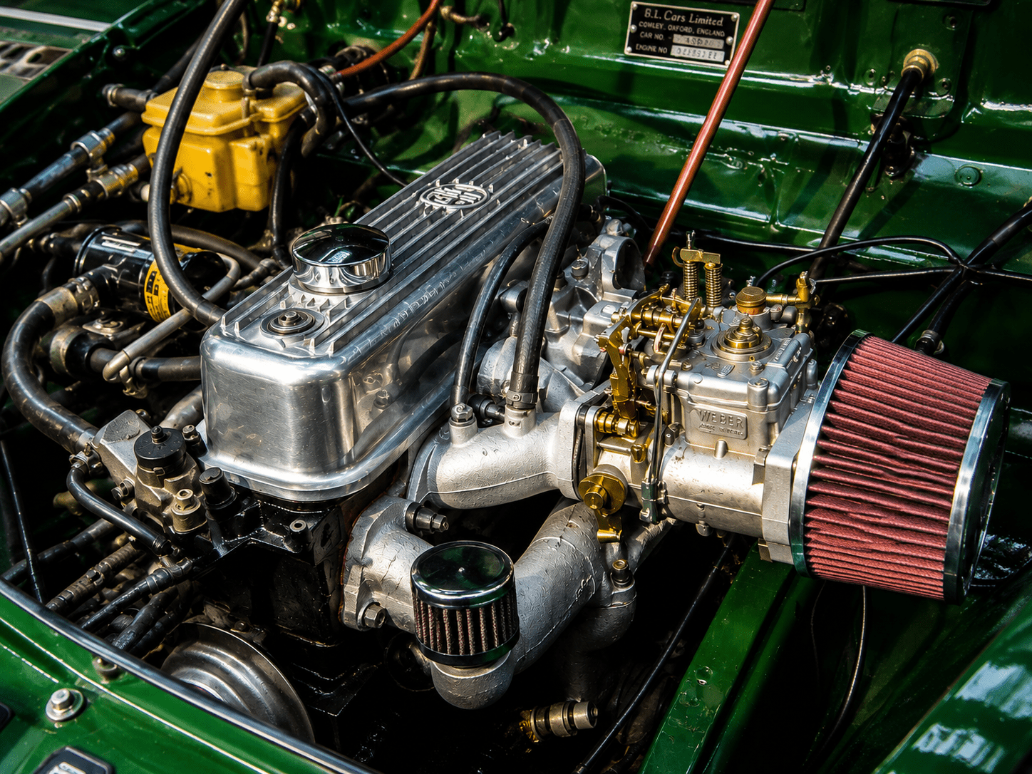
Two very different Webers: know which one you have
The DCOE is a sidedraught carburettor: it mounts horizontally, drawing air from the side of the engine. It has two chokes (barrels) per unit, each with its own set of jets, and is at its best on engines with individual runner intake manifolds where each barrel feeds one or two cylinders directly. Twin DCOEs on a four-cylinder engine is the classic configuration: one carburettor per side, each feeding two cylinders. Triple DCOEs on a six-cylinder provide one carburettor per pair of cylinders. It is a genuinely excellent racing set-up and a somewhat demanding road set-up. There is no choke in the conventional sense. Cold starting requires technique. And by “technique” we mean patience, a specific sequence, and the resignation that comes from accepting the car will need nursing for the first minute of every cold start regardless of how well set up it is.
The Weber 32/36 DGV and the DGES are downdraft carburettors: they mount vertically on a conventional intake manifold and are progressive twin-choke units, meaning the second choke only opens once the first is past a certain point. They were designed specifically for road use, provide an excellent balance between performance and drivability, and are a genuine upgrade over the factory carburettor on a large number of classic British engines. They have a proper choke, start reliably in cold weather, and do not require you to develop a personal relationship with the accelerator pump circuit before they will function correctly. If you want Weber performance with significantly fewer complications, the DGV is the one to consider. Everything that follows primarily addresses the DCOE, but the DGV principles of float level, idle circuit, and jetting are directly transferable.
Understanding the circuits: the key to everything
The DCOE has several fuel circuits that operate across different throttle positions. Understanding which circuit is responsible for fuelling at any given point is the difference between systematic tuning and random jet swapping. The latter approach is more common and less effective than its popularity would suggest.
The idle circuit handles fuelling at closed or near-closed throttle. It is controlled by the idle jet and the idle mixture screw, and it is responsible for far more of the driving experience than its name implies. According to Weber’s own technical documentation, the idle circuit is responsible for approximately 80 percent of normal driving operation. At motorway speeds with a light throttle, you are on the idle circuit. When cruising through town at a steady throttle, you are predominantly on the idle circuit. Getting this right matters more than getting the main jet exactly right, and most tuning problems that manifest as rough running or poor economy at light throttle are idle circuit problems rather than main circuit ones.
The progression circuit bridges the gap between the idle circuit and the main circuit. It is fed by the idle jet and controlled by a series of small holes in the throttle barrel wall, called progression holes, that are progressively exposed as the throttle opens. The throttle plate position at idle relative to these holes is critical: the plate should cover approximately half of the first progression hole at idle, no more. If it is set too far open, the progression circuit is active at idle and the whole tuning baseline is corrupted. This is one of the most commonly incorrect settings on second-hand DCOEs and one of the most overlooked.
The main circuit takes over at larger throttle openings and is controlled by the main jet, air corrector jet, emulsion tube, and main venturi. It is also affected by the accelerator pump circuit, which delivers a shot of raw fuel when the throttle is opened quickly to prevent the flat spot that would otherwise occur as the transition from progression to main circuit happens.
Choosing the right DCOE: 40 or 45?
The most common question from anyone new to DCOEs is whether to use 40s or 45s. The numbers refer to the barrel diameter in millimetres. Bigger is not better. The barrel size should be chosen to suit the main venturi (choke) size, and the main venturi size should be chosen to match the engine. A venturi that is too large for the engine gives poor air velocity through the barrel, inadequate fuel atomisation, and a flat and uninspiring power delivery below peak rpm. This is not what anyone buying DCOEs was hoping for.
The formula: divide the engine capacity in cubic centimetres by the number of cylinders, then divide by 100, then multiply by the peak power RPM divided by a constant derived from the engine type. In practice, for most road and mild performance applications on four-cylinder British engines of 1600 to 2000cc, venturi sizes of 32 to 36mm are appropriate, fitting comfortably in 40 DCOE barrels. A 45 DCOE can accommodate the same venturis and is a sensible choice if further engine development is planned. For most road applications, the 40 DCOE is the right answer. The person who fitted 45 DCOEs to a standard 1600cc engine because they “give more power” has, in almost every case, given themselves more problems rather than more power.
Starting point jetting for the main circuit: main jet size equals the venturi (choke) size multiplied by four. A 36mm venturi therefore starts with a 144 or 145 main jet. Air corrector jet: main jet plus approximately 60, so around 200 to 205 for the example above. Idle jets: 40/F9 or 45/F9 for most 1600 to 2000cc engines, with the F9 designation referring to the air bleed size. These are starting points, not finished settings. The rolling road session that follows initial setup will refine them. Consider them the equivalent of zeroing a rifle scope: necessary but not the same as shooting accurately at distance.
Buying second-hand: what to check before spending any money
Most DCOEs in the classic car market are second-hand. New ones are expensive. Second-hand ones are sometimes inexpensive for a reason. Check these things carefully before any money changes hands.
Serial numbers: look for the serial number stamped on the top of each carburettor. On a matched pair, these should be the same or very close. Unmatched pairs can have different progression hole drillings between units, which means they will never balance properly regardless of how well everything else is set up. Buy matched pairs or buy single units and accept the implications. This is not a minor point: a mismatched pair bought cheaply will cost significantly more in time and frustration than a matched pair bought at a fair price would have.
Throttle spindle wear: with the carburettor in hand and the butterflies closed, try to wiggle the spindle. Any perceptible play means worn spindle bushes, which allows air to bypass the butterfly and enter the engine unmetered. This leak cannot be tuned out. It produces an erratic idle and inconsistent progression that no amount of jet changing will cure. Spindle bushes can be replaced but the job requires precision and specialist equipment. Factor the cost into your offer or walk away.
Throttle quadrant condition: the connection between the throttle quadrant and the spindle wears with use and produces the same symptoms as spindle wear. Check that the quadrant is firmly attached and that there is no slop between it and the spindle. A worn quadrant is cheaper and easier to address than spindle wear but is still worth negotiating on.
General condition: look for fire damage, heat distortion of the carburettor body, damaged or missing jet access plugs, and evidence of ham-fisted previous tuning attempts (stripped screw heads, damaged jet faces, and progression holes that have been drilled larger by someone who had a theory). Check that the venturi size is embossed on the venturi itself, visible through the barrel from the air inlet side. DCOEs are very rarely sold ready-jetted for any specific engine: factor the cost of a jet kit and potentially new venturis into your budget before comparing prices.
Before touching a jet: the pre-setup checklist
Several things must be correct before DCOE tuning will produce useful results. Ignition timing must be confirmed and correct. There must be no vacuum leaks at inlet manifold gaskets, throttle spindles, or any other point in the induction tract. Valve clearances should be correct. The fuel pump must deliver the correct pressure: the DCOE is sensitive to fuel pressure in a way that the SU and Stromberg are not. Too much pressure forces fuel past the float needle valve and floods the carburettor. The correct range is 2 to 2.5 psi for most DCOE applications. Standard electric fuel pumps frequently deliver too much. A pressure regulator is not optional on a DCOE installation: it is part of the installation.
Float level: the foundation of everything else
If the progression holes are the most overlooked check, the float level is the most important. The float maintains a constant fuel level in the float bowl, and every circuit in the carburettor draws fuel from this reservoir. Too high and every circuit runs rich. Too low and every circuit runs lean, and the main circuit may starve under hard acceleration. Float level errors produce symptoms that look exactly like jetting errors and generate hours of futile jet swapping by people who have not checked the level first.
The float level on a DCOE is measured with the carburettor inverted and the float in the closed position, measuring from the gasket face to the underside of the float. Correct dimension varies by carburettor series: check the specific figure for your unit against the Weber factory manual or Des Hammill’s definitive reference book on the subject (more on which below). Adjust by carefully bending the tab on the float arm that contacts the needle valve. Small adjustments produce significant changes: work in fractions of a millimetre and recheck after each adjustment.
Throttle plate position: the check almost nobody does
Remove the threaded brass cap on the top of the carburettor barrel and look down at the throttle plate from above. The plate should cover approximately half of the first progression hole at the idle position, no more. If the plate is set further open, the progression circuit is feeding fuel at idle and you will be trying to set up the idle mixture with the wrong circuit active. The resulting idle settings will be wrong for all other conditions. Set this correctly before adjusting anything else on the carburettor, and set it on each barrel individually since they can differ.
Starting a cold DCOE: the technique
There is no choke on a DCOE. Cold starting requires the accelerator pump to prime the engine before cranking. The standard technique: pump the accelerator three to five times with the engine off to inject fuel through the pump jets, then crank with the throttle slightly open. If the engine fires but will not idle, gentle periodic blips of the throttle provide enough fuel to keep it alive until it warms sufficiently to idle on its own. If five pumps fail to start it, try the flooded approach: hold the throttle fully open and crank for five to fifteen seconds to clear excess fuel, then close the throttle and attempt to start normally.
This does not become natural immediately. Give it a week and it will feel no more complicated than starting a car with a conventional choke. In the first few days it will feel like negotiating with something that has decided not to cooperate and is enjoying the experience. This is a normal part of DCOE ownership and passes.
Setting the idle and mixture screws
With the engine at full operating temperature, the throttle plate correctly positioned relative to the progression holes, and the float level confirmed, set the idle speed using the throttle stop screws. On older style DCOEs (DCOE 2, 9, 18 and similar), the idle mixture screws should be set to between three quarters of a turn and one and a half turns out from gently seated. On the later style DCOE 151 and 152 with the additional air bleed screws under white plastic caps, the range is two and a quarter to three turns out. If you need more than two turns out on an older unit to achieve a reasonable idle, the idle jets are too small. If you have shut them to half a turn or less, the idle jets are too large.
Adjust each mixture screw independently in small increments, a quarter turn at a time, and listen for the fastest idle speed at each setting. The fastest idle at the correct idle speed setting indicates the best mixture for that barrel. Repeat on each barrel. On a twin DCOE installation this means four mixture screws, two per carburettor. Take notes. The mixture screws interact with idle speed: adjusting one will change the idle speed, requiring a corresponding adjustment to the throttle stop screw.
Balancing twin DCOEs
Balance is to twin DCOEs what diaphragm condition is to the Stromberg: the foundation that everything else depends on. An unbalanced pair will not tune correctly regardless of jetting. The balancing sequence on a DCOE installation is barrel-to-barrel within each carburettor first, then carburettor-to-carburettor between the pair.
The balance screws on the DCOE linkage equalise the throttle opening between carburettors. A vacuum gauge or purpose-built airflow meter (Carbalancer, Uni-Syn, or Carbtune) is used to compare the airflow through each barrel. Hold the meter against each barrel intake in turn, and record the readings. All four barrels on a twin DCOE installation should read the same. Adjust the throttle balance linkage to equalise the carburettors to each other, and use the carburettor’s internal barrel balance adjustment to equalise the barrels within each unit.
A lesser-known tip on the Carbtune manometer style: the vacuum ports on the intake manifold or trumpets are sometimes used for balance measurement rather than direct airflow at the intake bell. Both methods work, but the intake bell measurement is more immediately relevant to what the carburettor is actually doing and is less influenced by manifold pulse effects. Try to access the airflow directly at the carburettor intake if the layout permits.
Triple DCOE on a six-cylinder: the same principles, more of them
Three DCOEs on a six-cylinder engine (as fitted to some Lotus, Alfa Romeo, and various tuned British six-cylinder applications) follows the same principles as a twin installation but requires balancing six barrels rather than four. The sequence is: balance barrel-to-barrel within each carburettor, then balance the three carburettors to each other. The centre carburettor on a triple installation typically has slightly different airflow characteristics due to its position in the induction system, and it is not unusual for it to require slightly different idle screw settings to achieve the same reading as the two outer units. This is normal and not a sign of a fault. The engine firing order determines which cylinders each carburettor feeds, and the inlet manifold design should ensure even pulse distribution between carburettors: if it does not, no amount of balancing work will fully cure the imbalance.
The accelerator pump: tuning without new jets
The accelerator pump delivers a squirt of raw fuel when the throttle is opened quickly, bridging the momentary lean condition that would otherwise occur as the main circuit comes on load. If the car hesitates on quick throttle openings despite correct idle and main circuit jetting, the accelerator pump circuit is the likely cause. The pump jet controls how much fuel is delivered: a larger pump jet delivers more fuel per stroke.
A lesser-known tuning approach: the accelerator pump metering hole in the DCOE can be carefully enlarged using a pin vice and numbered drill bits (sizes 61 to 80 cover the useful range) to increase the volume delivered per pump stroke. This avoids the need for a new pump jet and allows very fine adjustment. Work in small increments, test, and return to the same test conditions for each comparison: engine temperature, gear, road speed, and throttle rate all affect the result. If enlarging the hole produces a good initial response followed by a brief bog, the pump duration is too short for the engine’s requirements, and further enlargement is not the answer.
Stub stacks, velocity trumpets, and uprated air filters
The DCOE draws air through its barrel via a bellmouth inlet. What sits on that inlet significantly affects how air enters the carburettor and, by extension, how the engine performs. This is one of the most overlooked aspects of DCOE installation and one where the choices made have real consequences for both power and jetting.
Stub stacks and velocity trumpets: length matters
A stub stack (also called a velocity stack, velocity trumpet, or ram pipe) is a short bellmouthed tube that fits into the carburettor inlet. Its purpose is to create a smooth, accelerating airflow into the barrel, reducing turbulence at the inlet and improving the consistency of air delivery across the throttle range. Running a DCOE without any stub stack at all, with the bare butterfly visible from outside, is worse for induction efficiency than running even the shortest stack. Something is always better than nothing.
Stack length is a tuning variable with a specific and measurable effect on the power curve. Longer stacks increase the ram effect of the induction pulse at lower engine speeds, shifting torque toward the bottom and mid-range. Shorter stacks favour higher-rpm performance where the pulse tuning effect is less relevant and maximum airflow matters more. For a road engine, longer stacks (50mm to 75mm) give a more usable power characteristic with stronger pulling from lower revs. For a competition engine used predominantly above 5000rpm, shorter stacks prioritise top-end flow.
Standard stack lengths available for the DCOE are typically 25mm, 50mm, 75mm, and 100mm. The 50mm is the most practical starting point for a road engine: long enough to deliver a noticeable improvement over a bare barrel, short enough not to create clearance problems in an engine bay that was not designed with triple sidedraught carburettors in mind. Stacks are available in polished aluminium and carbon fibre for those who consider the engine bay an aesthetic project as well as a mechanical one, which is not an unreasonable position when the carburettors in question look like they do.
Uprated air filters: K&N, ITG, and Sprint Filter
Running a DCOE completely open, without any air filtration, is standard practice in competition but inadvisable on the road. Unfiltered air on a road car introduces dust, grit, and whatever else is in the atmosphere into the barrels and, via the jets, into the engine. On a freshly rebuilt engine with new needles and jets this matters considerably. The compromise is a high-flow performance filter that provides adequate protection without restricting the airflow that makes the DCOE worthwhile in the first place.
The K&N RC series pod filters are the most widely used uprated filters for DCOE and sidedraught carburettor installations. They fit over the stub stack and use an oiled cotton gauze element that flows substantially more air than a paper element while providing genuine filtration. K&N produces specific sizes to fit the OD of standard DCOE stub stacks: confirm the outer diameter of your stacks before ordering, as there is no universal fit across all stack sizes and carburettor configurations. ITG Filters (a British manufacturer) and Sprint Filter (Italian, popular in motorsport) are well-regarded alternatives offering similar filtration efficiency with various materials and sizes.
The filter should always be fitted to the stub stack rather than directly to the carburettor face. Running a pod filter without a stack between the filter and the carburettor allows the filter media to influence airflow directly at the inlet, which disrupts the smooth bellmouth entry that the stack exists to create. The stack smooths the airflow; the filter protects the engine. Both are needed; the order matters.
K&N filters require periodic cleaning and re-oiling using the K&N Recharger kit. The cleaning interval depends on operating conditions: road use in dusty conditions requires more frequent attention than occasional use on clean roads. A filter that is over-oiled deposits oil residue on the carburettor inlet which, while not immediately catastrophic, is unnecessary and affects airflow. Apply oil sparingly after cleaning, allow it to soak into the gauze for twenty minutes, and remove any excess before refitting.
The jetting implications of changing the air intake setup
This is the section most owners discover by experience rather than preparation, usually because the engine starts running oddly after a new filter installation and nobody told them to expect it. Changing the air intake arrangement on a DCOE changes the jetting requirements. Full stop. The original jetting was calibrated for a specific airflow characteristic, and fitting open stacks or a pod filter where a cold air box previously sat alters that characteristic enough to require re-jetting.
The typical effect of switching from a closed cold air box to open stacks with pod filters: the main circuit runs leaner due to the increased airflow. Richer main jets are generally required: enriching by 5 to 10 jet sizes (for example from 125 to 130 or 135 mains) is a common starting point after switching to open stacks, though the exact requirement varies with the specific engine and installation. The idle and progression circuits may also need attention. Always re-establish the baseline after any significant intake change and treat the jetting as if it were a fresh setup rather than assuming the previous settings carry forward.
Heat soak is a related concern with open stacks and pod filters that is worth understanding before installation. An open stack draws air from the immediate engine bay environment rather than from outside the bonnet. Engine bay air is considerably warmer than ambient air, particularly after a run in traffic, and hot air is less dense than cold air. The practical result: the engine runs slightly leaner on hot air than on cold, and the mixture can shift noticeably between a cold start on a cool day and a hot restart after sitting in traffic on a warm one. A cold air induction arrangement, routing a proper duct from the front of the car to the carburettors, addresses this and is worth considering on a road car where consistent drivability matters as much as peak power.
One final point about open stacks that is technically a practical consideration but is often treated as an additional feature: the induction noise. A pair of DCOEs with 50mm polished stacks and K&N filters, at full throttle through the gears on an open road, produces an induction roar that is either the most characterful sound in the British classic car repertoire or an antisocial disturbance, depending on the listener and their proximity to a residential area. It is loud. It is distinctive. It is, for most people who have fitted DCOEs to a classic British car, approximately half of the point.
The rolling road: an investment, not an optional extra
A DCOE installation can be set up to run acceptably well using the baseline jetting formulas, correct float level, and careful attention to the idle and progression circuits. This is what this guide enables. It cannot, however, be set up to the same standard as a rolling road session, and anyone who tells you otherwise is either an exceptionally gifted road tuner with an unusually well-equipped test environment or is optimistic to a degree that practical experience will eventually correct.
The rolling road operator can produce consistent, repeatable test conditions, apply load across the full power range, measure power and torque directly, and read the exhaust gas composition accurately across all operating conditions simultaneously. Home road testing can do approximately none of these things with equivalent reliability. Budget for a rolling road session as part of the installation cost, use the baseline setup from this guide to get the engine running safely and reasonably, and let the rolling road operator refine from there. The combination of informed home preparation and professional final setup produces a better result than either alone.
Common problems and their causes
- Flooding: float level too high, fuel pressure too high (regulator required), or needle valve not sealing. Check fuel pressure first: it is the most common cause of flooding on a freshly installed DCOE and the one most often overlooked.
- Flat spot on progression: idle jets too small, throttle plate too far open at idle (bypassing the progression circuit), or accelerator pump not delivering enough fuel. Check throttle plate position before changing jets.
- Rough idle that will not settle: vacuum leak at manifold gaskets or throttle spindles, mismatched pair (check serial numbers), or progression holes active at idle due to incorrect throttle plate position.
- Rich at idle, cannot lean off: float level too high, or idle jets too large. Confirm float level before changing jets.
- Lean at all throttle positions: fuel pressure too low, blocked filter, or float level too low. The DCOE is particularly sensitive to fuel starvation under load.
- Won’t start cold: normal for DCOE if technique is not established. Review the cold start procedure. If the car floods instead of starting, the accelerator pump volume may be too high or the fuel pressure too high.
The one book worth buying
Des Hammill’s “How to Build and Power Tune Weber DCOE and Dellorto DHLA Carburettors” (Speedpro series, ISBN 978-1903706756) is the reference that every serious DCOE and DHLA owner should have on the shelf. Pegasus Auto Racing Supplies, one of the most respected Weber specialists in the world, recommends it unreservedly. Eurocarb, the UK’s leading Dellorto and Weber parts supplier, helped compile information for it. It covers venturi selection, jetting theory, strip and rebuild, rolling road setup, and troubleshooting in the depth that a magazine article cannot. It is not expensive. The money it saves in random jet purchases and unnecessary specialist visits pays for it several times over.
For related reading: our SU carburettor guide and Zenith-Stromberg guide cover the constant depression alternatives, our ignition timing guide covers the timing confirmation that must precede any carburettor work, and our spark plug diagnosis guide covers reading plugs to confirm the results of jetting changes.
This page contains affiliate links. If you click a link and make a purchase, Classic Car Hub may earn a small commission at no extra cost to you.