The clutch on a classic British car is one of those components that works without requiring any thought for years, and then stops working at a moment when thought is precisely what you do not have time for. The driver of an MGB who discovers at a junction that the clutch pedal has developed a one-way relationship with the floor is not in a position to calmly consider the root cause. The owner who knows how a hydraulic clutch system works, what the early warning signs of impending failure are, and what to do about them before the junction incident, is in a considerably better position.
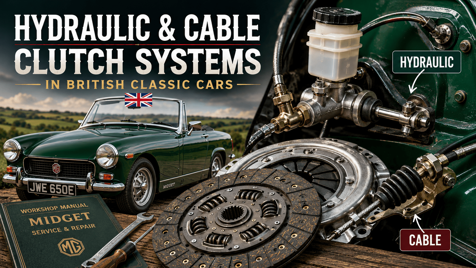
Classic British cars divide into two clutch system types: cable and hydraulic. Both operate the same basic clutch mechanism (a spring-loaded friction plate that connects the engine to the gearbox) but do so through fundamentally different means, and the service requirements, adjustment procedures, and failure modes are specific to each type. This guide covers both, with specific notes on the cars most commonly affected and the particular quirks that the workshop manual tends to understate.
Which system does your car have?
Cable clutch: Triumph Spitfire and GT6 (all marks), Triumph Herald and Vitesse, the classic Mini, Ford Cortina Mk1 and Mk2, and the Hillman Imp all use a cable to connect the pedal to the clutch fork. The cable runs from a pivoting pedal through the bulkhead and along the underside of the car to a fork on the gearbox bellhousing. No fluid involved. No bleeding required. Adjustment is mechanical and straightforward when the cable is in good condition.
Hydraulic clutch: MGB, MGA, MG Midget from 1961, Austin-Healey range, Triumph TR4 through TR6, Triumph 2000 and 2500, Triumph Stag, and Morris Minor all use a hydraulic system with a master cylinder under the bonnet and a slave cylinder at the gearbox. The system is essentially a miniature brake system: fluid pressure transmits the pedal movement to the clutch fork. The MGB shares its clutch fluid reservoir with the brakes, which is worth knowing before either system is run low.
The cable clutch: how it works and how to adjust it
Pressing the clutch pedal pulls the cable, which moves the release fork, which pushes the release bearing against the diaphragm spring fingers on the pressure plate. The spring fingers deflect, reducing the clamping force on the friction disc, which allows the disc to stop turning and the gearbox input shaft to slow down independently of the engine. Releasing the pedal reverses all of this in a fraction of a second. The cable is doing all the mechanical work and its condition directly determines the quality of the pedal feel.
Cable clutch adjustment is necessary because the cable stretches slightly under normal use and the friction disc wears down over time, both of which change the effective length of the operating mechanism. The symptom of an under-adjusted cable is a clutch that disengages very high up the pedal travel (little free play) or not fully at all. The symptom of an over-adjusted cable is a clutch that slips because the release bearing is being held against the pressure plate fingers by the cable even when the pedal is not depressed, causing continuous wear on the bearing and gradual release of the spring pressure.
The adjustment point varies by car. On the Triumph Spitfire and GT6, there is an adjuster at the gearbox end of the cable where the cable inner connects to the release fork. On the Mini, the adjuster is typically at the pedal end. Correct free play at the pedal is generally specified in the workshop manual for the specific car, but as a general guide approximately half an inch to three-quarters of an inch of free movement before resistance is felt is the target on most cable clutch applications. Check the figure for your specific car and use it: the general guide is a starting point, not a substitute for the correct specification.
When adjusting the cable, also inspect it. Run a clean cloth along the outer sheath and check for cracking, kinking, or chafing where the cable contacts bodywork or brackets. The inner cable should move freely within the outer sheath: gripping the inner cable where it exits the outer and moving it manually (with the outer held still) should produce smooth, light movement. Resistance indicates either a seized cable or a kinked sheath. A cable that is seizing should be replaced rather than adjusted: the seizure will worsen, the pedal effort will increase, and the cable will eventually break at its weakest point, which is invariably the least convenient moment.
Cable clutch replacement
Replacing a clutch cable is a straightforward job on most classic British cars once the routing is understood. Photograph the original cable routing before removing it: the replacement must follow exactly the same path, with no sharp bends, no contact with exhaust components, and no routing near moving parts. The cable on a Triumph Spitfire runs through a specific path beneath the body and must be correctly threaded through its guides to prevent premature wear on the outer sheath. The Mini cable routes through the engine bay in a way that looks logical but has one non-obvious guide clip that the replacement must engage correctly.
Disconnect the inner cable from the release fork, unscrew the adjuster at the accessible end, and thread the cable out of its guides and through the bulkhead grommet. Thread the new cable in reverse order. Adjust to the correct free play specification before driving and recheck after 200 miles as the new cable settles into its sheath.
The hydraulic clutch: how it works
The master cylinder converts pedal effort into hydraulic pressure. Inside the master cylinder a piston moves within a bore, pushing fluid through the hydraulic line to the slave cylinder. The slave cylinder piston extends under this pressure, pushing the release fork and therefore the release bearing against the clutch. The hydraulic system is self-adjusting in the sense that it compensates for the free play changes caused by friction disc wear: unlike a cable clutch, no periodic adjustment is required. The system maintains the correct operating geometry automatically provided the seals are intact and there is no air in the circuit.
The flexible hydraulic hose between the metal line and the slave cylinder ages and can fail internally without any obvious external sign. An internal collapse of the hose creates a one-way restriction: fluid passes from master to slave (clutch disengages) but cannot return freely (clutch does not re-engage fully, or pedal sticks down). This specific fault is frequently misdiagnosed as a master cylinder failure or a worn clutch. If the pedal goes down normally but is reluctant to return, and the clutch appears to be dragging, replace the flexible hose before condemning anything else.
Bleeding the hydraulic clutch
Air in the hydraulic system compresses where fluid does not, producing a soft, spongy pedal that travels further than it should and may not fully disengage the clutch. Bleeding removes the air. The process is essentially identical to bleeding brakes: open the bleed nipple on the slave cylinder, allow fluid to exit, close the nipple, repeat until no bubbles are visible in the fluid.
Before bleeding anything, check the slave cylinder bleed nipple position. This is particularly important on MGB and MG Midget applications: many aftermarket replacement slave cylinders have been supplied with the bleed nipple and inlet incorrectly positioned for approximately forty years, and a significant proportion of replacement cylinders arrive with the bleed nipple at the bottom of the cylinder rather than the top. Air rises. If the bleed nipple is at the bottom, air cannot exit regardless of how long you bleed. The fix is to remove the nipple and the inlet fitting and swap them: the threads are the same size and this takes five minutes. If you have been bleeding an MGB clutch for an afternoon with deteriorating patience, this is almost certainly the explanation. You are not doing it wrong. The cylinder was assembled incorrectly.
Standard two-person bleeding method: one person maintains the fluid level in the master cylinder reservoir, one person operates the pedal. The procedure is: open the bleed nipple half a turn, have the assistant push the pedal slowly to the floor, close the nipple before the pedal is released, allow the assistant to release the pedal, repeat. The critical step is closing the nipple before the pedal returns: if the nipple is open during the return stroke, air is drawn back into the system from the nipple end, which eliminates any progress made on the down stroke.
The gravity bleeding method requires no assistant: open the bleed nipple, ensure the reservoir is full, and allow fluid to flow under its own head of pressure. Fluid carries air bubbles with it. Top up the reservoir regularly to prevent air being drawn in from the top. Gravity bleeding is slower than the two-person method but reliable when performed with patience. The cable-tie method used by some MGB owners for stubborn cases: disconnect the slave cylinder pushrod from the release fork, push the slave piston fully into the cylinder, secure it in the retracted position with a cable tie, then gravity bleed with the piston retracted. This minimises the internal volume of the slave cylinder and reduces the space available for air to hide.
Symptoms of clutch wear and failure
Hydraulic system faults
Pedal sinks slowly to the floor with the engine running and clutch held down: the master cylinder is bypassing internally. The seal within the master cylinder bore is worn and allows fluid to pass the piston without operating the slave. The clutch may appear to work normally for individual gear changes but will not hold sustained disengagement. Replace the master cylinder or rebuild it with a seal kit.
Fluid loss from under the bonnet near the pedal box: master cylinder external seal failure. The fluid is escaping past the external seal rather than the internal one. Replace or rebuild the master cylinder. On cars where the clutch and brake share a reservoir, loss of clutch fluid is simultaneously loss of brake fluid: do not ignore this.
Fluid on the ground beneath the gearbox: slave cylinder external seal failure. Replace or rebuild the slave cylinder. The slave cylinder on most classic British applications is an accessible component and replacement is a short job compared to the clutch replacement it may be preventing.
Spongy pedal that travels further than usual: air in the hydraulic system. Bleed the system as described above. If the sponginess returns rapidly, there is a leak introducing air: locate and address the leak before bleeding again.
Clutch drags (will not fully disengage, gear changes difficult): insufficient hydraulic travel at the slave cylinder. Possible causes: air in system, collapsed flexible hose, seized slave piston, or on cable systems, a cable out of adjustment or partially seized.
Clutch friction disc and mechanical faults
Clutch slipping: the engine revs rise under load without a corresponding increase in road speed. Either the friction disc is worn below usable thickness, the clutch free play is incorrectly adjusted (too little, keeping the release bearing partially engaged), or oil contamination has reduced the friction coefficient of the disc. Oil contamination can be confirmed by a burning smell and by the characteristic jerky engagement as the oil-soaked disc alternately grips and slips. The source of the contamination (rear crankshaft seal, gearbox input shaft seal) must be found and addressed before a new clutch is fitted, otherwise the replacement disc will suffer the same fate.
Judder on take-up: a shudder through the car as the clutch is engaged from rest. Causes include oil contamination, a glazed or uneven friction disc surface, worn or broken engine mounts allowing the engine to rock as the clutch loads up, or a warped pressure plate. Engine mount condition is the first thing to check before condemning the clutch: a significantly worn engine mount produces a judder that perfectly mimics a clutch problem and costs considerably less to address.
Clutch engages very high up the pedal travel: normal on a new clutch that has not yet bedded in. Increasingly high engagement point on an existing clutch indicates a worn friction disc approaching the end of its useful life. When engagement reaches the very top of pedal travel the disc has worn through to the rivets or backing plate, and further use will damage the flywheel and pressure plate. Replace the clutch before this point is reached.
Rattling or chirping from the bellhousing area at idle, disappearing when the clutch pedal is depressed: worn release bearing. The bearing is in contact with the pressure plate fingers when the pedal is not depressed on some designs, and a worn bearing produces a distinctive chirping or rumbling noise that stops when the pedal is pressed because the bearing then rotates at the same speed as the pressure plate. Replace the release bearing at any clutch change, regardless of whether it is making noise: the cost of the bearing is trivial relative to the labour involved in reassembly.
Clutch replacement: the procedure in outline
Replacing the clutch friction disc, pressure plate, or release bearing on a classic British car requires removing the gearbox. This is the job that causes people to reconsider whether the symptoms are really that bad, and in some cases that reconsideration is entirely rational: a clutch that is slipping slightly but has six months of usable life remaining is not an emergency if the budget for gearbox removal does not currently exist. When replacement is necessary, the correct approach is to replace the friction disc, pressure plate, and release bearing simultaneously: fitting only the friction disc and leaving the original pressure plate and bearing is a false economy that will require the gearbox to come out again sooner than it should.
Raise the car on axle stands with adequate clearance to work underneath. Remove the propshaft (mark its orientation on the differential flange before removal to preserve balance). Support the gearbox with a transmission jack or a trolley jack with a wood block, as the gearbox is significantly heavier than it looks and will not hold itself up once the mounting is removed. Disconnect the hydraulic line or cable at the gearbox end. Remove the gearbox crossmember. Remove the bellhousing bolts and slide the gearbox rearward, keeping it level to avoid hanging the weight on the input shaft while the gearbox is partially withdrawn.
With the gearbox removed, mark the relationship of the pressure plate to the flywheel before unbolting it: the assembly was balanced as a unit and refitting in the same orientation preserves that balance. Unbolt the pressure plate evenly in a diagonal sequence, releasing the spring pressure gradually to avoid distorting the cover. Inspect the flywheel face for scoring, blueing from heat, or cracks. Light scoring can be machined out; heavy scoring or cracking requires a replacement flywheel. Check the pilot bush in the centre of the crankshaft: this small bush or bearing supports the gearbox input shaft and wears over time, producing a slight vibration at idle. Replace it if there is any perceptible play.
Fit the new friction disc using a clutch alignment tool. The alignment tool holds the disc centred in the pressure plate while the bolts are tightened, ensuring the gearbox input shaft will pass through the disc splines during reassembly. Do not attempt to centre the disc by eye: the tolerance is too tight for visual alignment to work reliably. Tighten the pressure plate bolts evenly in a diagonal sequence to a light torque (typically 12 to 15 lb ft on most classic British applications), not the maximum effort that might seem appropriate given the spring pressure involved. Apply a very small amount of high-temperature grease to the input shaft splines: enough to allow the disc to slide freely, not enough to contaminate the friction surface. Assembly is the reverse of removal. Bleed the hydraulic system before the first drive and check the fluid level.
For related reading: our brake fluid and bleeding guide covers the bleeding procedure and DOT fluid specification in more detail, our workshop safety guide covers the correct procedures for supporting a car during gearbox removal, our MGB buyers guide and TR6 buyers guide cover clutch condition assessment as part of the pre-purchase inspection, and our gearbox oil guide covers the correct oil to use when the gearbox is refitted.
This page contains affiliate links. If you click a link and make a purchase, Classic Car Hub may earn a small commission at no extra cost to you.